Specification Sheet

TR / DB Installation Kit

Mounting and interface hardware designed for transformer rectifier and drainage bond installations with protected analog inputs, external power access, and field-serviceable wiring interfaces.

Overview

Installation Specification

The TR / DB Installation Kit supports structured installation in cabinet and panel environments while preserving durability, protection, and identifiable asset configuration.

Mounting Options

Low-profile cradle format with a 112.2 mm x 49.5 mm x 12 mm envelope and countersunk through-hole mounting for compact cabinet and panel installations.

Environmental Design

Integrated fuse, gas discharge tube, precision surge clamp, and filtering stages support protected CP measurement wiring in exposed field environments.

Electrical Interfaces

Designed for retrofit compatibility and efficient installation on existing or new TR / DB infrastructure using poke-in field wiring contacts.

Protection & Identification

On-board 1-wire cradle identification and QR / serial marking support lifecycle traceability, asset linking, and maintenance records within the portal.

AgentG4CP Cradle

Detailed Specification

Current AgentG4CP TR / DB installation kit capability set for mounting, field wiring, analog measurement interfaces, power access, identification, and PCB construction.

Mechanicals

  • Overall envelope: 112.2 mm x 49.5 mm x 12 mm
  • Housing material: ASA UV Stabilised Polymer
  • Cradle PCB: 112.5 mm x 48 mm
  • Mounting holes: 4.5 mm through holes with 8.96 mm x 90 degree countersink
  • Mounting hole reference positions shown at 31.2 mm and 78.7 mm along the cradle length
  • External housing and PCB views shown in the technical drawing

PCB Construction

  • 4-layer PCB, 1.6 mm thickness, black solder mask
  • FR4 TG135 laminate
  • ENIG finish, 1 uin gold
  • 1 oz / 0.5 oz copper stack with epoxy-filled and capped vias
  • Horizontal electroless copper plating with edge plating features
  • Minimum hole size: 0.2 mm
  • Outline tolerance: +/- 0.2 mm

Agent Interface

  • Main Agent-to-cradle connection via 10-position Mill-Max pogo connector
  • Interface includes CP common, +/- 100 mV inputs, CP input channels, external power, power enable, 3.3 V cradle supply, cradle ID, and ground
  • Dedicated 1-wire cradle ID EEPROM: 1 Kbit AT21CS11-STU10-T
  • JTAG / SWD programming and debug access provided for MCU and modem service workflows

Field Connections

  • 18-22 AWG TE poke-in wire contacts for field wiring
  • Analog field terminals: +/- 10 V input, common, configurable second voltage input, +/- 100 mV positive, and +/- 100 mV negative
  • External charge power terminal: 5-12 VDC
  • Dedicated power supply ground and earth terminals
  • External power supply ground is labelled isolated and should be transformer-isolated rather than switch-mode referenced

Analog Inputs

  • Channel A: +/- 10 V analog CP input with common reference
  • Channel B: configurable voltage input path for alternate ranges such as 10 V, 100 V, or 300 V
  • Channel B divider footprint supports resistor selection for keeping the Agent input below 10 V
  • Higher-voltage divider configuration supports up to 600 V components in the same footprint
  • Dedicated +/- 100 mV differential input channel for shunt, coupon, or low-level measurement applications

Identification & Marking

  • Unique cradle ID exposed to the Agent through the main pogo interface
  • 2D barcode and serial number marking provision
  • QR code provision: 10 mm x 10 mm
  • Cradle version marking shown as AgentG4 Cradle CP v1.3.0 on the PCB artwork

Mechanical

Technical Drawing

TR / DB installation cradle front, side, base, and PCB views for mechanical reference, mounting-hole review, connector orientation, and installation-envelope checks.
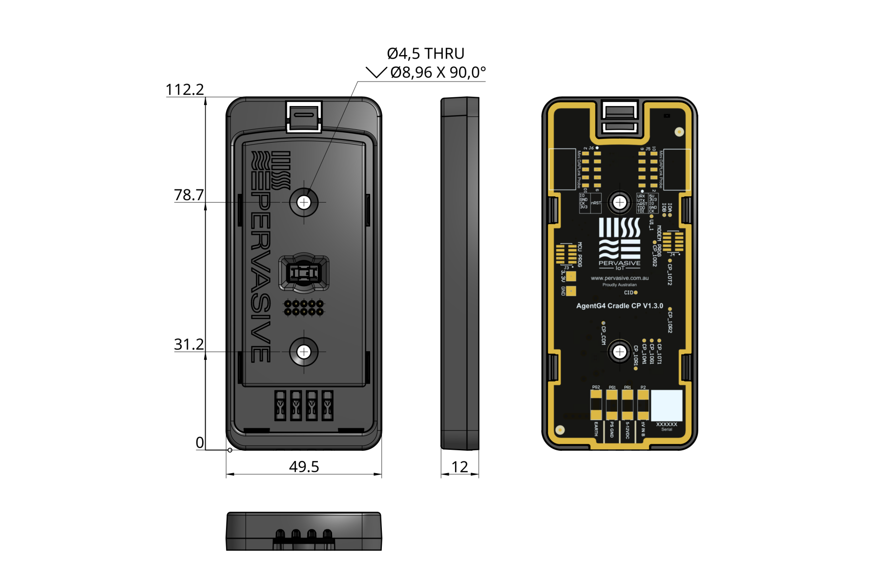
TR / DB installation cradle technical drawing showing mechanical dimensions, mounting holes, side profile, field terminals, and PCB layout

Protection

Circuit Protection

Protection features included in the AgentG4CP cradle schematic for exposed CP measurement wiring, configurable voltage input paths, low-level 100 mV measurements, and external power access.

10 V Input Protection

  • 75 V, 2 kA gas discharge tube surge protection on the +/- 10 V CP input path
  • 0.375 A, 125 V slow-blow SMD fuse protection on the analog input path
  • Bidirectional precision surge diode protection on the Agent-side analog input
  • 22 uH series inductor filtering ahead of the Agent interface

Second Voltage Input Protection

  • 150 V, 2 kA gas discharge tube surge protection on the configurable second voltage input path
  • 0.375 A, 125 V slow-blow SMD fuse protection on the field input
  • Precision surge diode protection and 22 uH series inductor filtering on the Agent-side path
  • Resistor-divider footprint supports alternate input ranges while limiting the Agent input below 10 V

100 mV Channel Protection

  • Dedicated +/- 100 mV positive and negative field terminals
  • 75 V, 2 kA gas discharge tube surge protection on both 100 mV input legs
  • Bidirectional precision surge diode protection on the low-level measurement channel
  • Earth-referenced surge path for exposed low-voltage CP measurement wiring

Power & Service Protection

  • External 5-12 VDC charge power input with separate power supply ground
  • Dedicated earth connection for surge and installation grounding
  • 3.3 V cradle supply, power enable, cradle GPIO, UART, JTAG, and SWD service lines routed through cradle interfaces
  • Programming and debug sockets support MCU and modem service access without disturbing field wiring